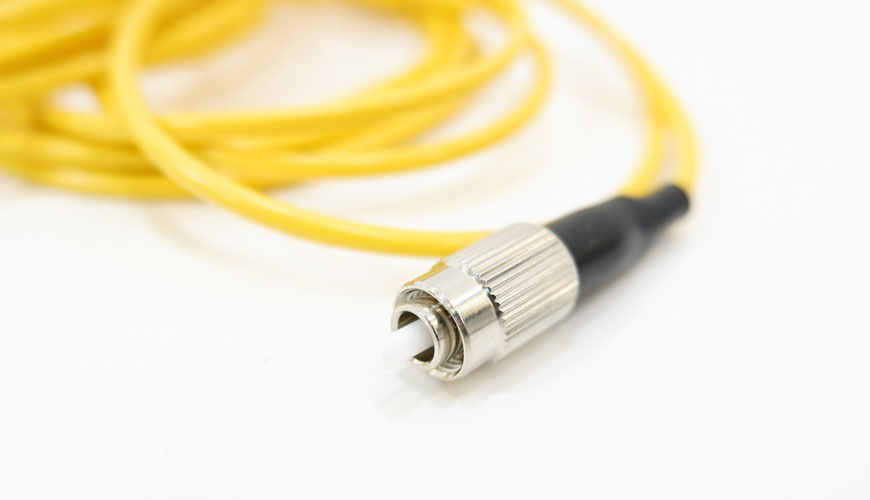

EUROLAB laboratory provides testing and compliance services within the scope of IEC 61300-3-17 standard. This part of the IEC 61300 standard is to describe methods for measuring the end face angle of flat or convex angled polished ferrules. Flat end face angle For polished rings, ring end face angle θ is defined as the angle between the plane perpendicular to the axis of the ring and the flat end face plane.

For spherically polished angled end face ferrules, the end face angle θ is the angle between the plane perpendicular to the axis of the ferrule and the straight line tangent to the polished surface in the fiber core in the nominal angle direction. Four methods are described for measuring the ferrule end angle:
Method 1: Automatic Interferometric Method
Because of its higher accuracy, method 1 is considered the reference method. In this method, the ferrule end face is placed on a tiltable micro-locator under a microscope with interferometric capability. A fixed holder can be used at the nominal value of the angle to be measured, but in this case the described alignment procedure cannot be applied and a reference angle plug, measured by other methods, must be used.
Method 2: Manual Interferometric Method
As in method 5, the ferrule end face is placed in a tiltable micro-locator under a microscope with interferometric capability. In this method, however, the ferrule is tilted by a micro-positioner until the surface of the end face is normal to the optical axis of the interferometer: this happens when the true value of the angle is reached. In the case of the convex polished ferrule end surface, this position is reached when the interference rings and the fiber are both symmetrical to the axis of rotation (see figure XNUMX). In the case of a flat polished ferrule, this position is reached when interference fringes disappear or are minimal.
Method 3 – Mechanical Profilometry Method
In this method, the end face angle is evaluated by profiling the end face ferrule with a surface analyzer. The ferrule is placed in a fixed holder at the bottom of the mechanical profilometer pen. The ferrule axis will be parallel to the stylus axis and the plug will be positioned at an angle to the pen scan direction. The end face angle of the ferrule is evaluated from the analysis of the resulting profile.
Method 4 – Reflected Light Method
In this method, a visible light He-Ne beam aligned along the ring axis is reflected by the ring end surface to strike a screen as a dot pattern. The screen is normal to and surrounds the ferrule axis.
In the case of a flat polished ring end surface, the dot pattern is typically a small, visible, approximately evenly illuminated circle with little additional deflection in the laser beam. In the case of a spherically polished ring end surface, the pattern is typically a small ring (Air disc) located at the center of a large circle of visible beams separated from the original laser beam. This small ring is caused by Fraunhofer diffraction of the He-Ne beam reflected from the spherical ferrule end surface containing a fiber or fiber hole as a centrally located aperture.
EUROLAB, with its more than 25 years of experience, state-of-the-art accredited laboratories and expert team, helps you get precise and fast results. Do not hesitate to contact our laboratory for your testing and certification requests.
To get an appointment, to get more detailed information or to request an evaluation, you can ask us to fill in our form and reach you.