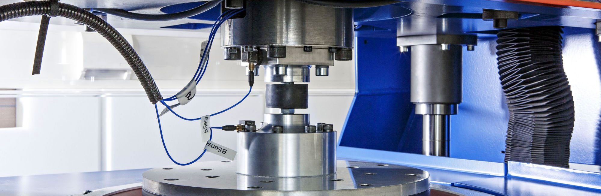
EUROLAB laboratory provides testing and compliance services within the scope of IEC 61300-3-2 standard. This part of the IEC 61300 standard specifies measurement methods for determining the dependence of loss in a single-mode fiber optic device on changes in polarization. This procedure focuses on measurements with a fixed wavelength source.

Therefore, this procedure is applicable to devices whose features at a single wavelength can represent features over the broader wavelength band. Typical examples of such devices are single-mode interconnect devices and passive components including connectors, splices, branching devices, attenuators, isolators, and switches.
The maximum observed change in conduction loss is called polarization-dependent loss (PDL). This standard applies to broadband devices, not narrowband devices such as filters and multiplexers. The reader refers to IEC 61300-3-29 for such measurements.
Two methods are described for measuring loss due to polarization. The all-states method determines the maximum variation in transmission loss by stimulating a representative set of all possible polarization states, including linear, circular, and elliptical. The Mueller matrix method determines sensitivity using a set of steady states and applying Mueller matrix mathematical analysis.
In this method, the device's response is determined using a power meter by rotating the source polarization over a representative set of all possible polarization states while the PDL monitors the transmission. The rotation can be performed in a deterministic or pseudo-random fashion.
The term deterministic refers to techniques that reproducibly scan a large subset of the entire polarization state space. This method scans the Poincare sphere along predetermined trajectories and produces a good approximation of full sphere coverage.
The term pseudo-random refers to techniques that scan polarization through a pseudo-random delay variation in the optical path, often using the distributed delay of optical fiber loops in motion.
The Mueller matrix method involves measuring the behavior of a device under test (DUT) when the input light is illuminated with a small set of well-defined polarization states. These measurements are followed by a matrix calculation to determine the PDL of the DUT. In general, there are two matrix formalisms that can describe and quantify the polarization behavior of light based on Mueller and Jones calculations. For fully polarized light, the Mueller and Jones formalisms are equivalent, as is required for PDL measurements. Since measurements with polarization instrumentation on only one side of the DUT directly obtain the necessary elements of the Mueller matrix, namely the elements corresponding to power ratios rather than field amplitude and phase, the test procedure described here uses Mueller's mathematics to determine the PDL.
Mueller matrix formalism requires an optical power representation of the performance of components. This matrix is a 16-element square matrix. Here, the polarization state (SOP) of light is defined as the 4-element Stokes vector. The Stokes vector of incident light multiplied by the Mueller matrix of the DUT gives the Stokes vector of the output light, which can be caused by transmission, reflection or scattering. In determining the PDL of a component using Mueller matrices, it is not normally necessary to specify the exact Mueller matrix, but rather only the first row of the matrix, which provides complete information about the light intensity but not the resulting polarization state.
The accuracy of the method depends on the source wavelength stability, the system signal-to-noise ratio, and the deviation in system birefringence.
EUROLAB, with its more than 25 years of experience, state-of-the-art accredited laboratories and expert team, helps you get precise and fast results. Do not hesitate to contact our laboratory for your testing and certification requests.
To get an appointment, to get more detailed information or to request an evaluation, you can ask us to fill in our form and reach you.
EUROLABreporting and certification activities, United Accreditation Foundation (UAF), Turkish Accreditation Agency (TÜRKAK) ve Enterprise Accreditation Foundation (EAF) based on the accreditation provided by the accreditation body. The Enterprise Accreditation Foundation (EAF) accreditation body is also a signatory of the United Nations (UN GLOBAL COMPACT) organization.